
In this video, Clint Cooper from AP Emissions explains diagnostic procedures for catalytic converter problems arising from issues relating to air and/or conceptual grouping of air, fuel, and spark.
Episode Overview
• Recap of previous videos. (00:8)
• Discussion of diagnostic procedures for catalytic converter problems. (00:22)
• The first diagnostic test is to do a visual inspection of the system (0:32)
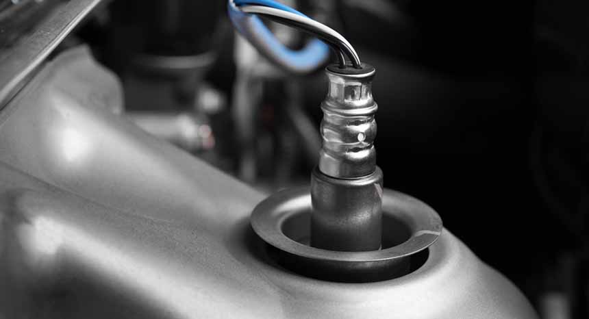
• Test and replace any lazy upstream oxygen or air fuel sensors. (0:55)
• Proper voltage for an 02 sensor is explained. (1:13)
• Procedures to test an upstream air fuel sensor. (1:34)
• Where to look for and how to patch exhaust leaks. (1:44)
In our previous videos, we talked about how catalytic converters work, what triggers a catalyst inefficiency code, what causes thermal damage and catalyst poisoning, and how those problems reduce the efficiency of our catalytic converter.
In this video, we will discuss some diagnostic procedures for catalytic converter problems, arising from issues relating to air and/or conceptual grouping of air, fuel, and spark.
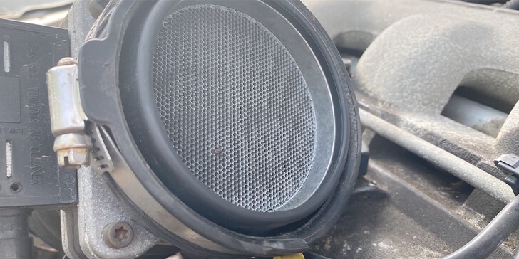
Our first step is to do a visual inspection for worn out gaskets and vacuum leaks. I do a smoke or bubble test if you suspect vacuum leak, but can’t find it. Check your mass airflow sensor and clean or replace as needed. Use a scan tool or a multi-meter to note quick increase from two to seven grams per second at idle, to maybe 15 or 25 grams per second at 2500 RPMs.
Test and replace any lazy upstream oxygen or air fuel sensors. A recent CARB emissions roadside emissions check found that half of all catalytic converter failures were due to a lazy upstream sensor. Check upstream 02 air fuel sensors, and make sure that they’re not lazy, weak, or foul. Voltage for an O2 sensor should rise to 850 millivolts, then it should drop to 150 millivolts. It should never drop below zero. Voltage should switch once every two seconds to five times per second. The voltage rise time is less than 80 milliseconds. Voltage fall time should be less than 100 milliseconds. In order to test your upstream air fuel sensor, you should add some metered propane, or force a lean condition with a vacuum leak downstream from the mass airflow sensor and note a quick response.
Look for and patch any exhaust leaks. Common location for exhaust leaks are near hangers and gaskets, and where two surfaces are welded together. Check engine compression to make sure that pressure in the combustion chamber is within spec and evenly balanced across cylinders. In our next video, we’ll be looking at catalytic converter diagnostic tips related to fuel.